Week 2 - Sensors and connectivity

Introduction
During the Week 2 lab, we used example sketches to access the sensors and peripherals on the Seeed Studio Xiao nRF52840 Sense board and expansion board base. The results of my collaboration with fellow student, Linto Thomas, are below.
0. Built-in IMU and Microphone
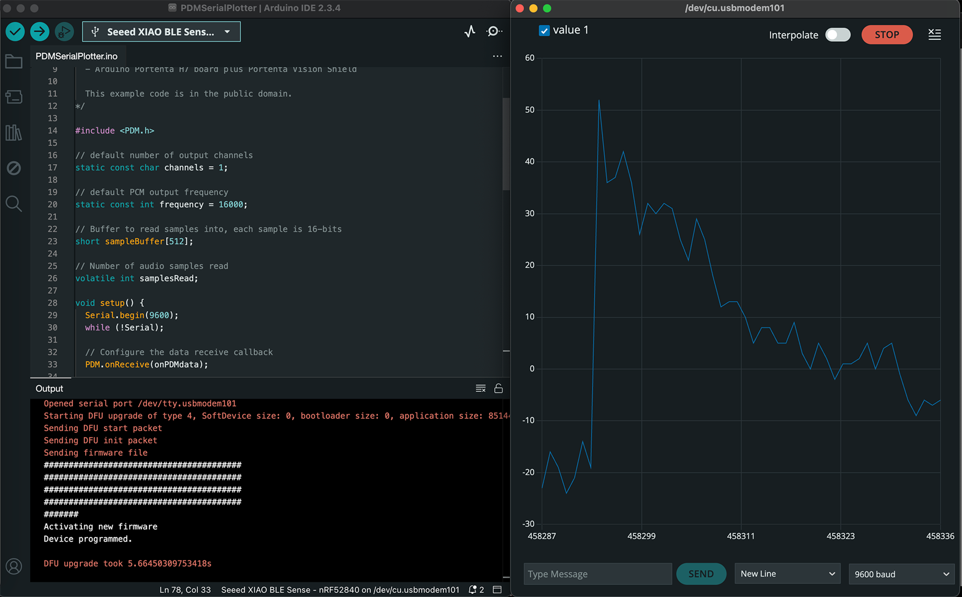
We first collected accelerometer, gyroscope, and temperature data from the built-in IMU and printed it to the serial monitor.

We also accessed the microphone and used the serial plotter to visualize the signal.
1. OLED Display
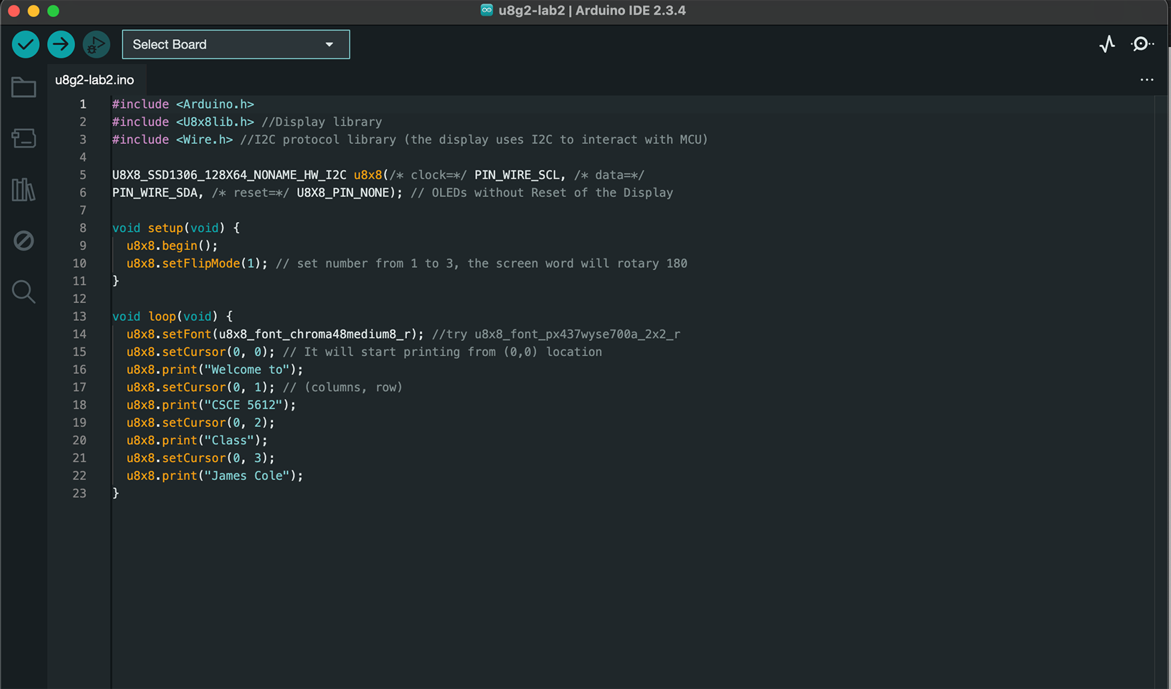
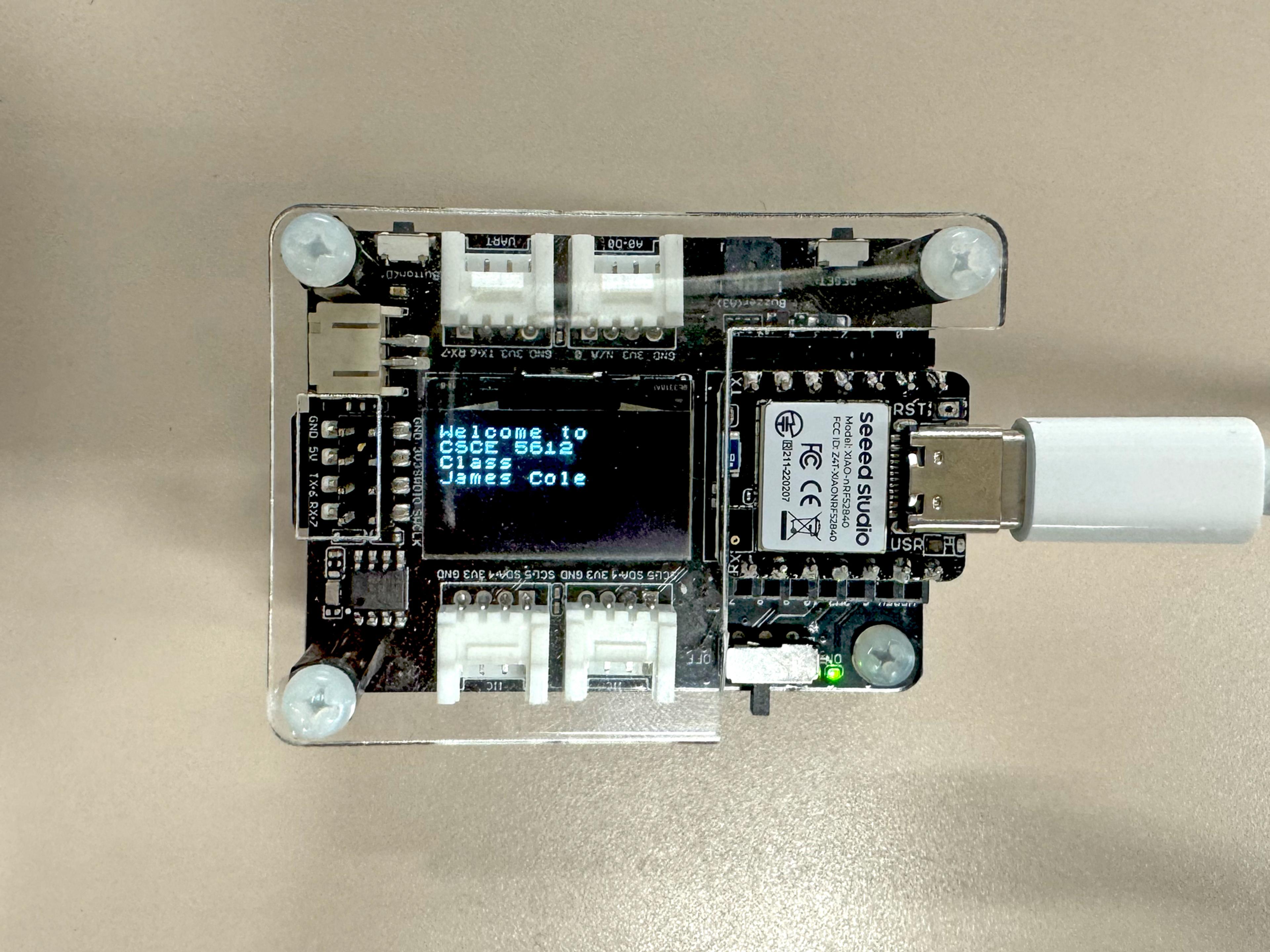
In this exercise, we used the example sketch to printing text on the OLED display. I slightly modified the example sketch by adding a line to display my name, which is visible in the images below.
2. MicroSD Card
The sketch below writes data to the SD card. We experienced some inconsistencies when trying to view the .txt file written to the SD card, but were able to view the file on a Windows laptop. The output file Linto Thomas generated from this sketch can be downloaded here (right click and select Save Link As....).

3. RTC (Real-time clock)
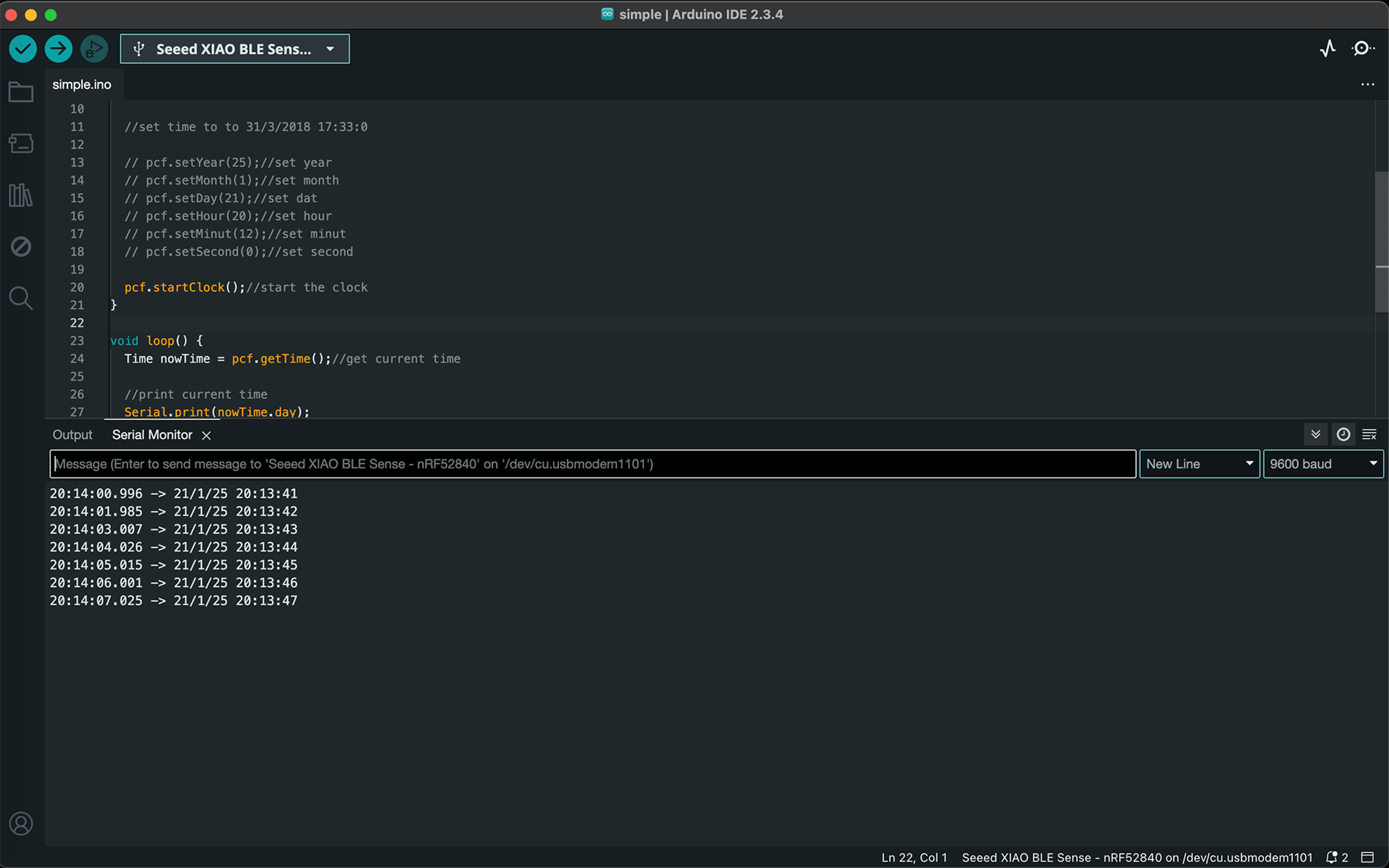
The screenshot below shows how the RTC is set. The sketch was first uploaded with the clock set to the the current time (using Central Time) during the lab. The methods for setting the time were then commented out and the board was flashed again so the time would not reset whenever the device is turned on.
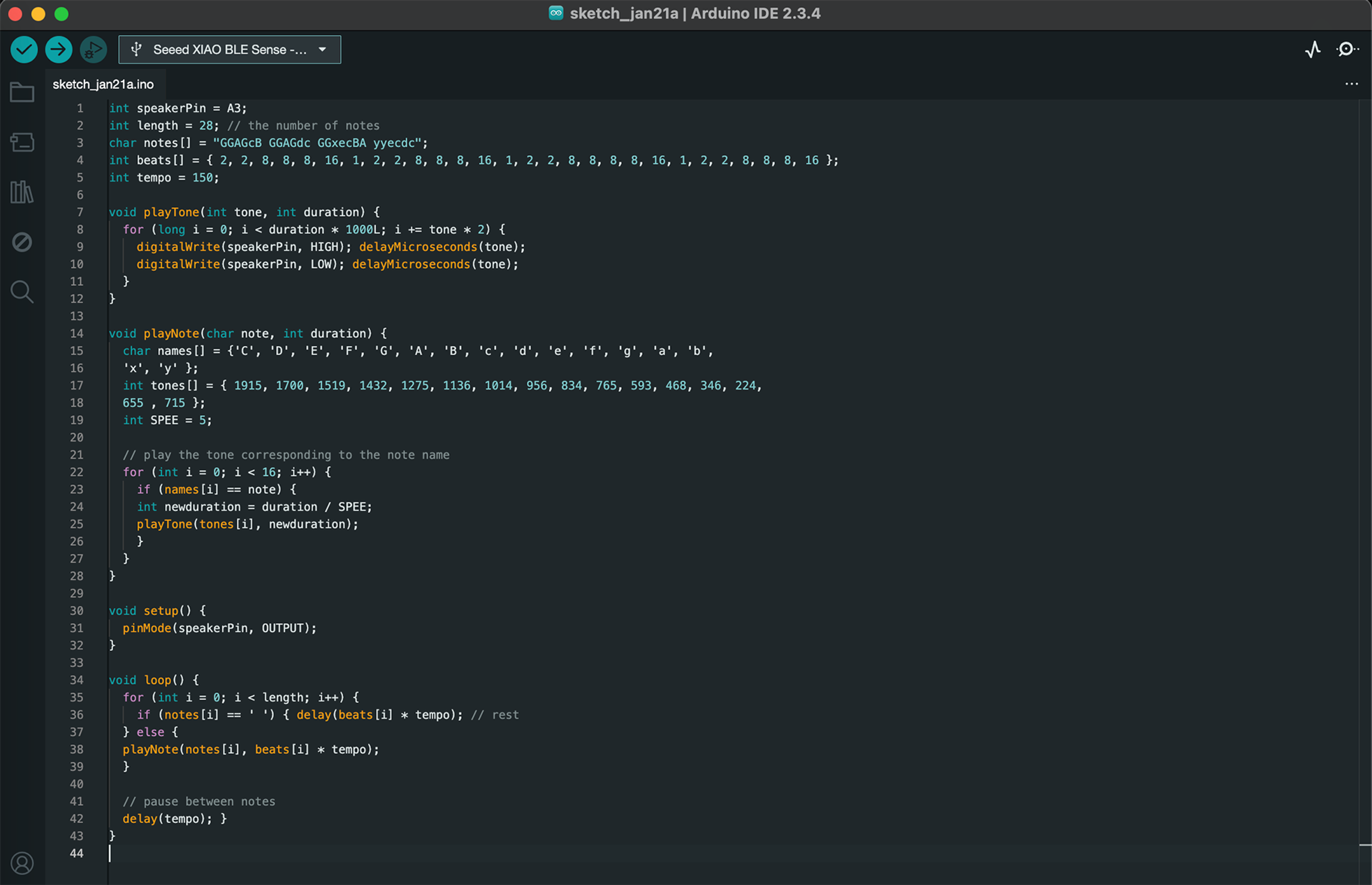
4. Buzzer
This sketch plays the "Happy Birthday" song using the buzzer. The melody is audible in the video below.
5. Bluetooth Low Energy
This sketch (right) enables Bluetooth connections to the board. Line 42 of the code was changed to BLE.setLocalName("James Cole"); so I could locate the board amongst the many other BLE devices in the lab. The mobile screenshot (right) shows the successful connection, which is also visible in the Arduino IDE serial monitor.

Other updates
I migrated this website from GitHub pages to a customized CMS built with Next.JS and Sanity Studio that is deployed using Vercel. I use a similar setup for my personal website. While the initial configuration is somewhat complex, it is otherwise simple to customize the website and create new posts in a consistent format.

