Weeks 8 and 9 - Finite State Machine and Object Detection

In this lab, we used the OV2640 camera module on a XIAO ESP32S3 Sense to perform object recognition and control a finite state machine. Our first task involved capturing images of 5 different toy cars to use for model training.
Data collection
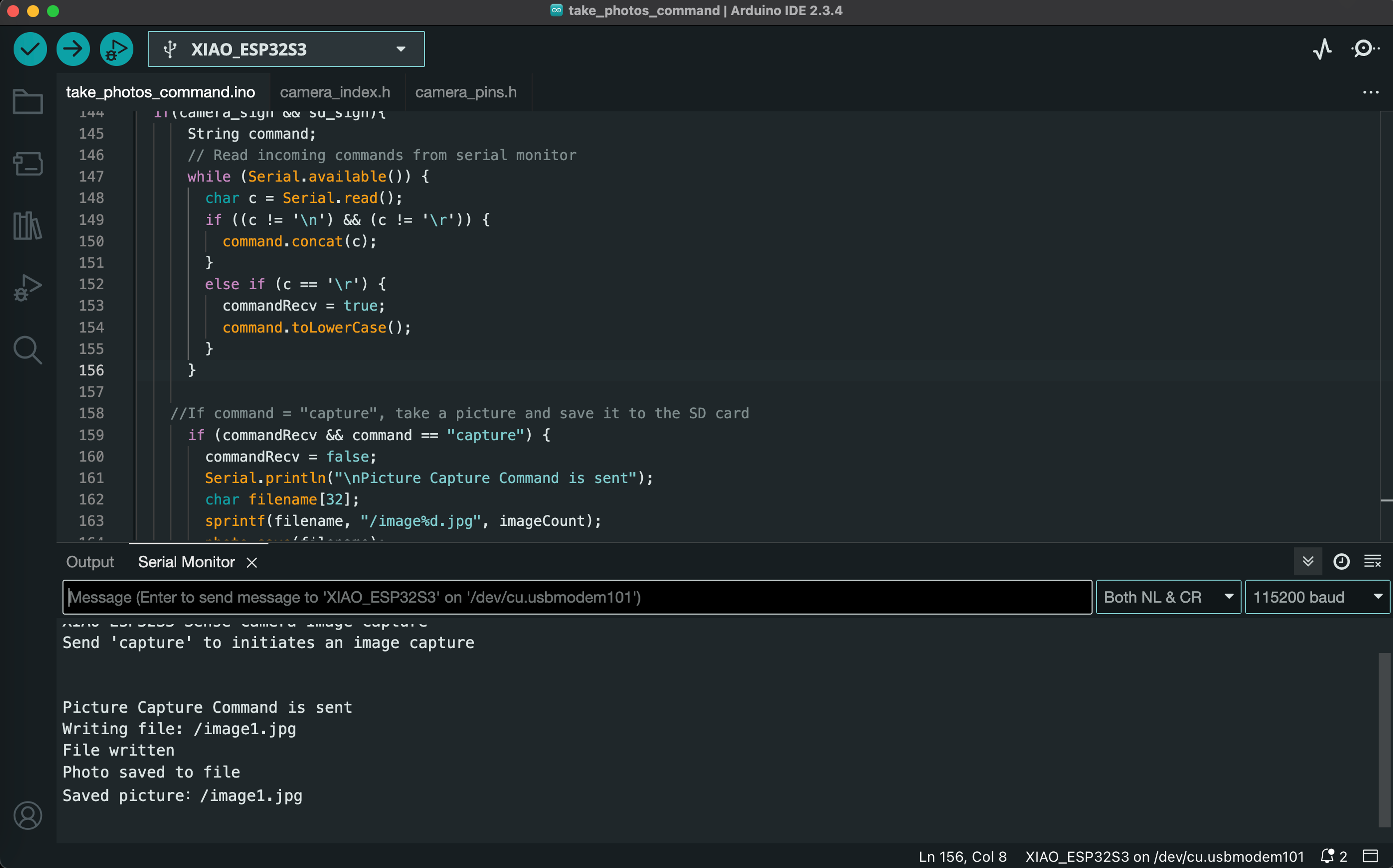
We first programmed our microcontroller to use the camera and store the photos on a SD card. Our first successfully captured image shows half of my face peering over my laptop.

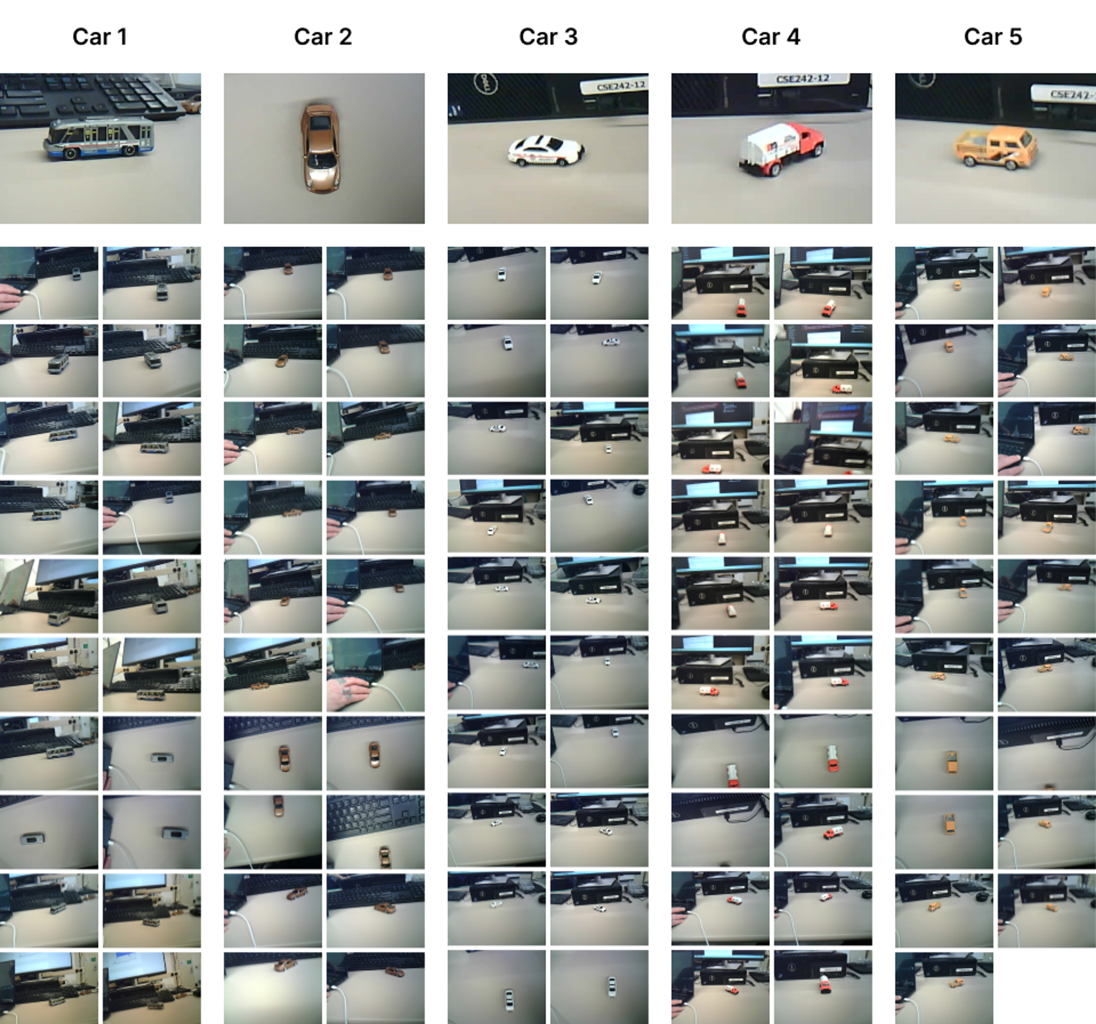
We then captured ~20 images for each of 5 different toy cars (~100 images total). The images feature a variety of angles, background elements, and degrees of motion blur to provide the model a diversity of data for training. Our full dataset is available here.
Model training
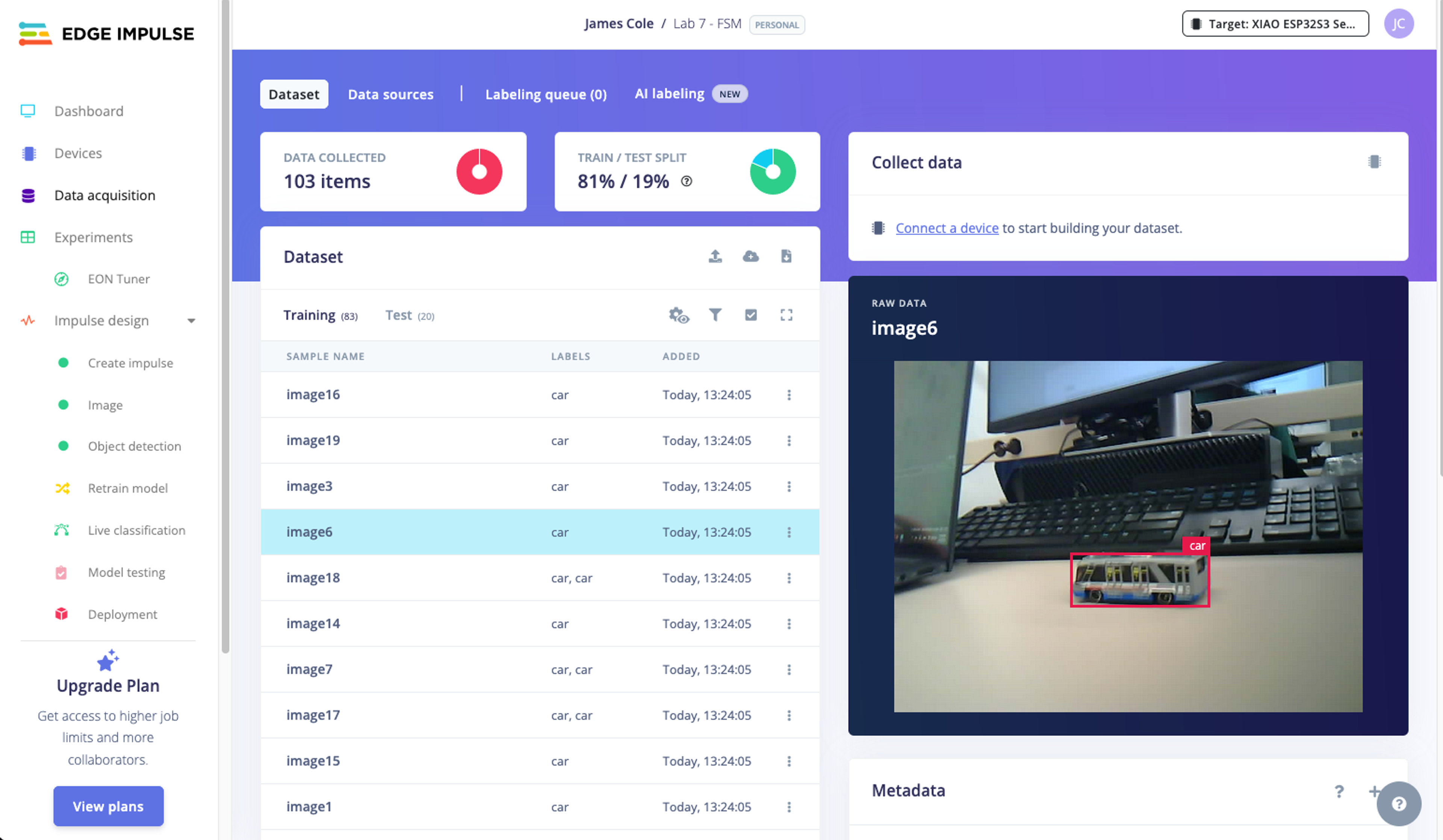
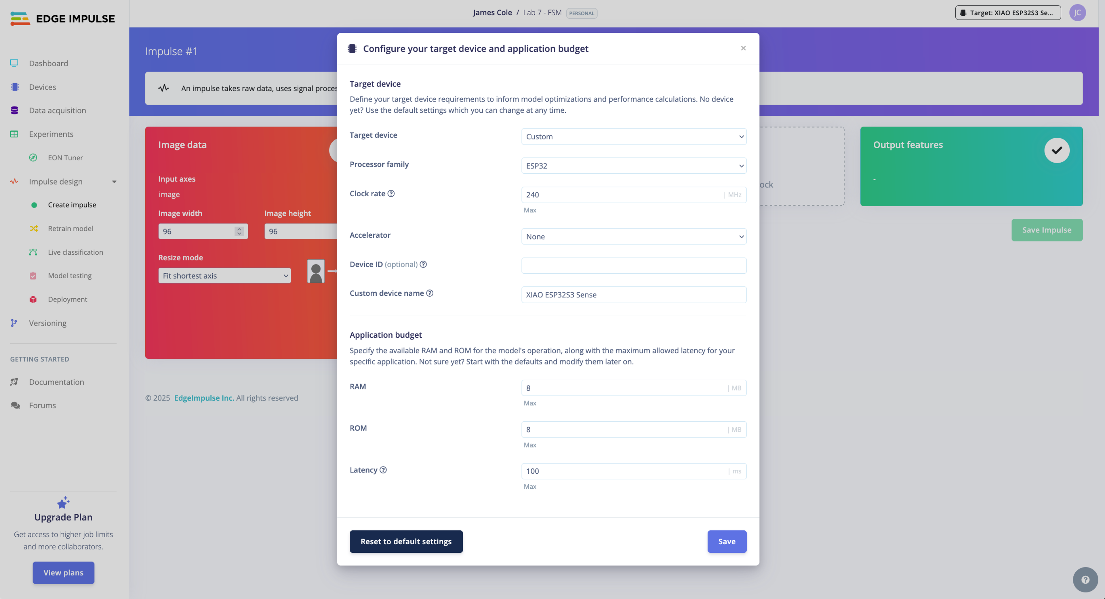
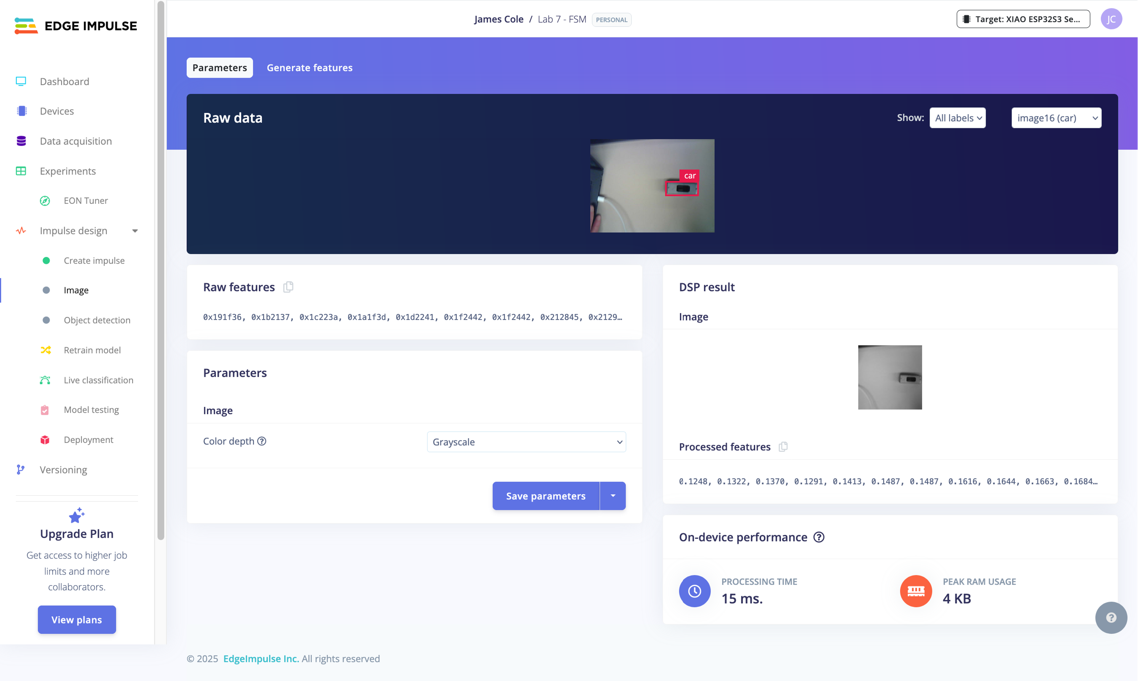
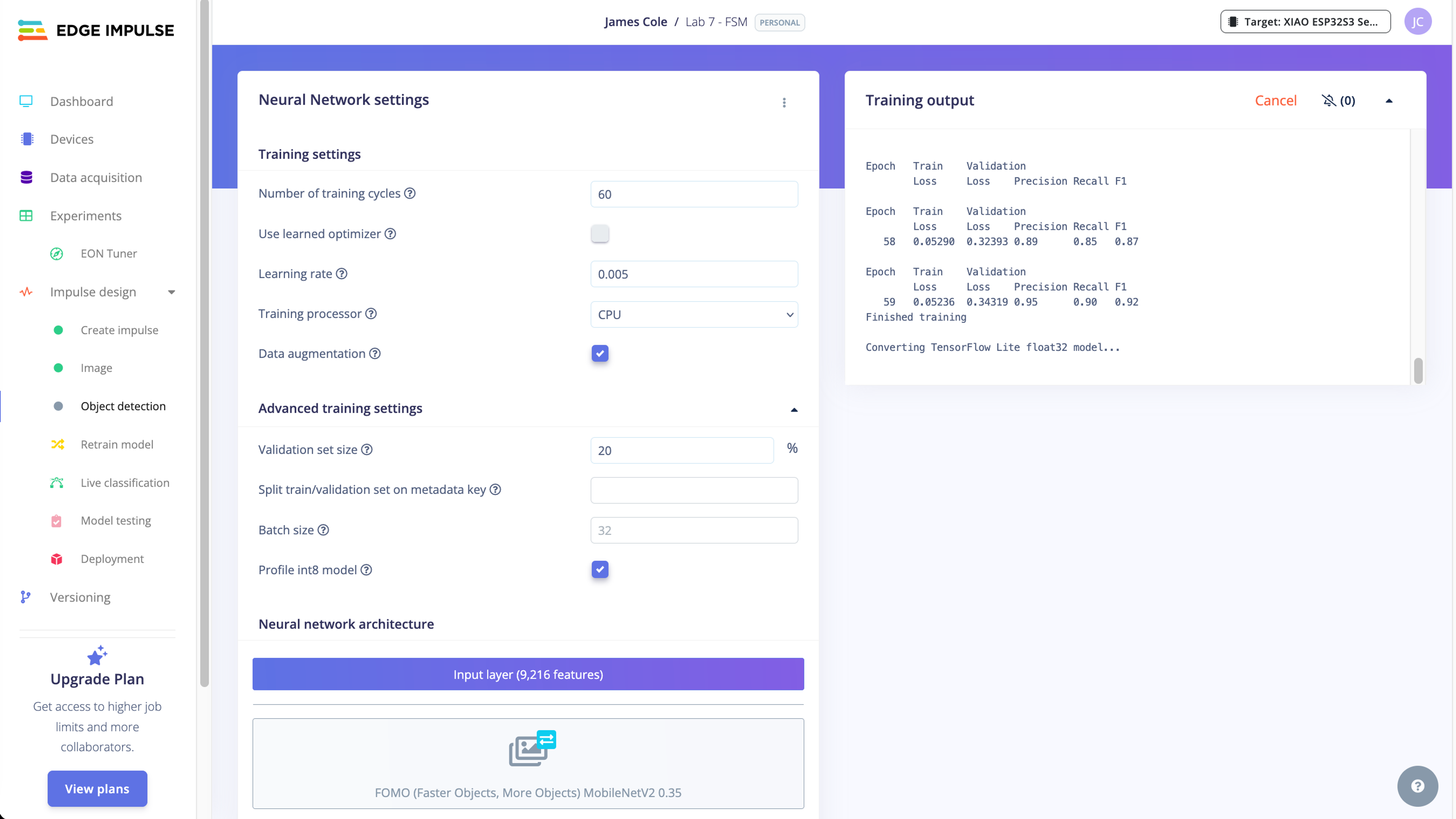
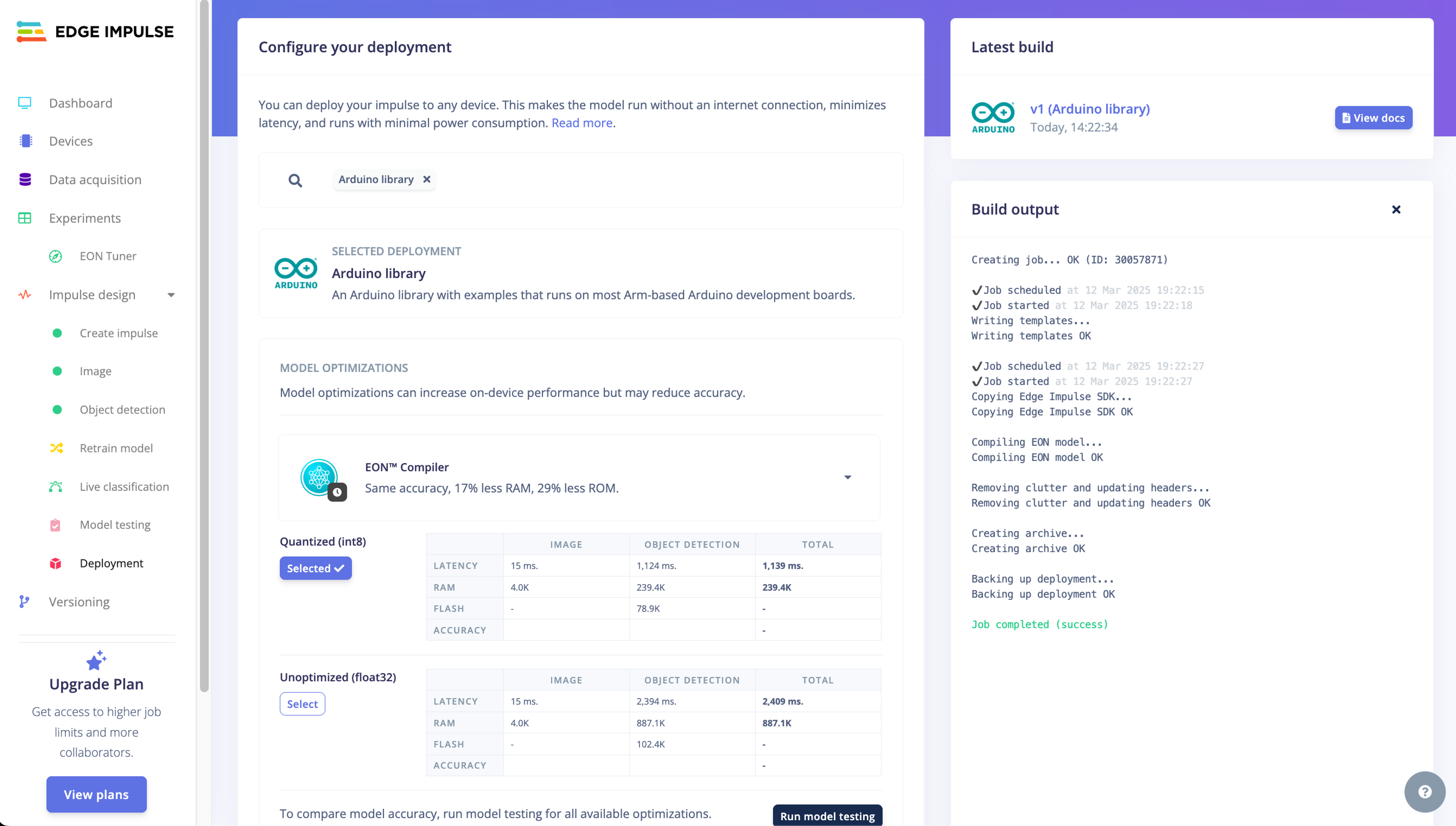
After collecting a sufficient number of images, we used Edge Impulse to train a FOMO (Faster Objects, More Objects) model for object detection. This process involves labeling each image by drawing a bounding box around the subject (e.g., cars), creating an impulse, defining model hyperparameters, training the model, and exporting the trained model. Importantly, the image data needed to be preprocessed by converting the color space from RGB to Grayscale and resizing the images to 96x96 pixels. Some of the particularly blurry images were removed.
Edge Impulse does not currently provide a default device configuration for the XIAO ESP32S3, so these settings were customized based on the board specifications.
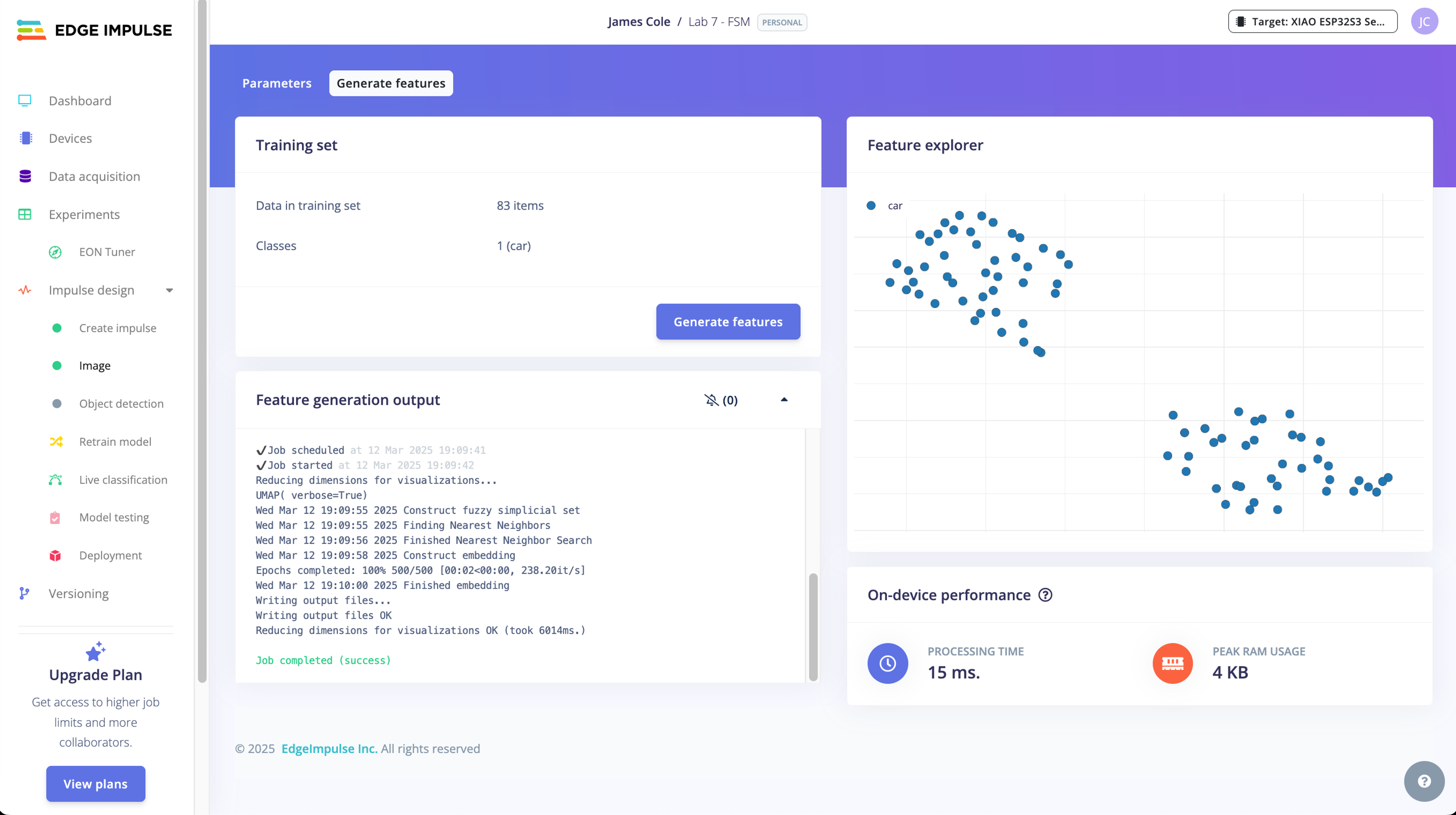
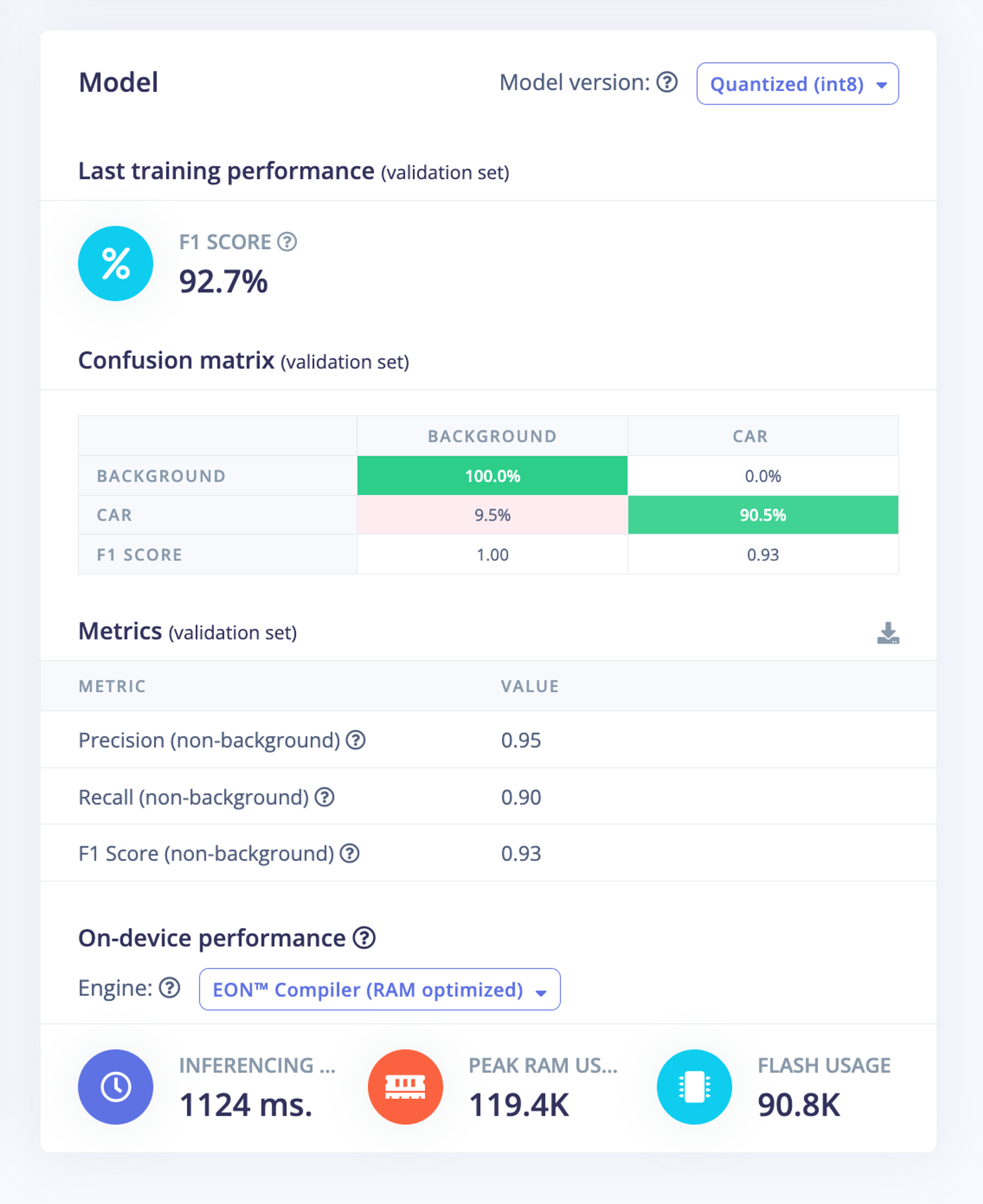
Our model achieved a top F1 score of 0.93 on the validation dataset, indicating that it will likely be able to identify cars when deployed.
Inference
The model export from Edge Impulse includes the files necessary to run inference on our XIAO. However, we needed to make two small adjustments before testing the model.
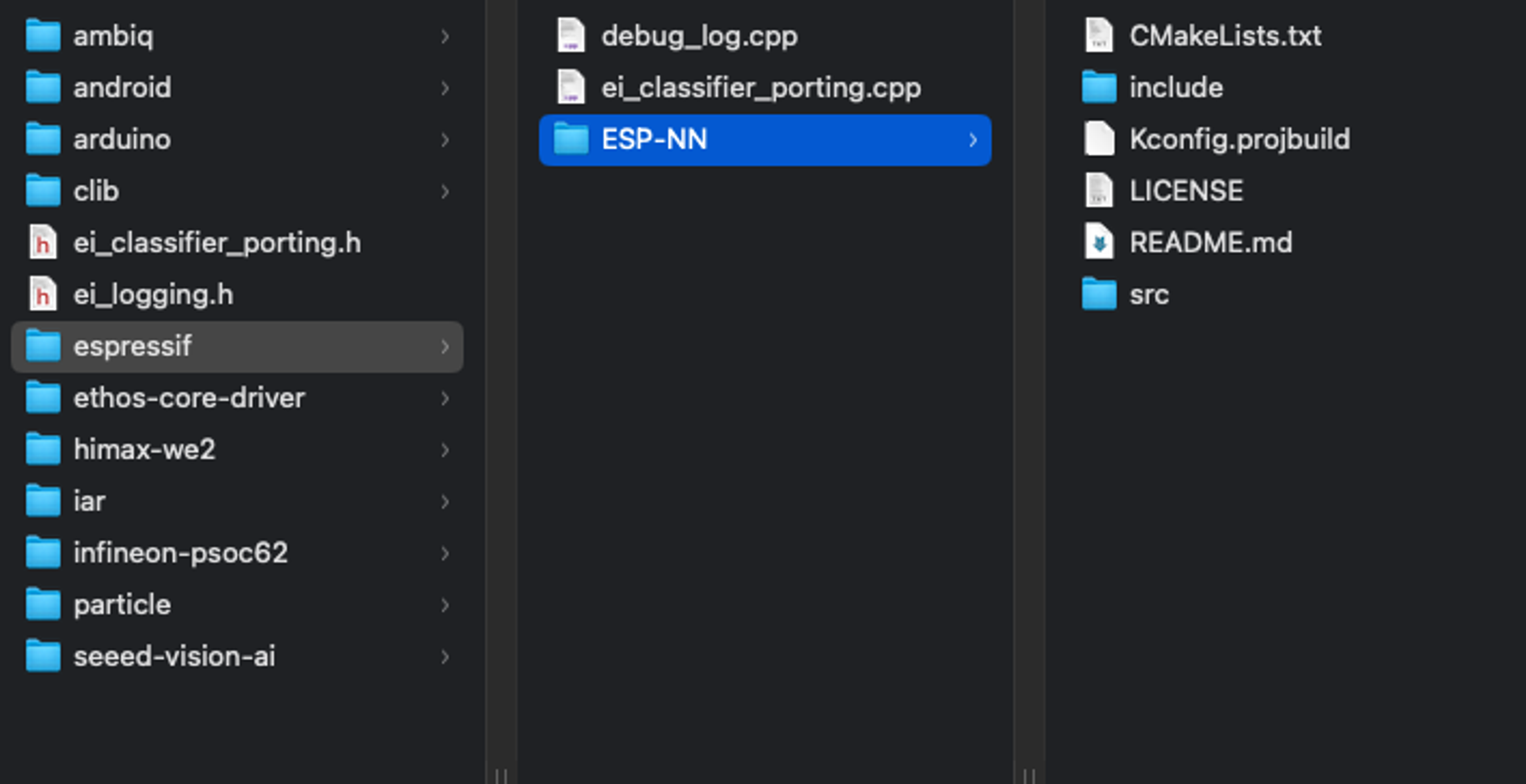
After uploading the ZIP file downloaded from Edge Impulse, we enabled the ESP NN Accelerator by replacing the ESP-NN folder in our esp32_camera sketch with the one made available here. More detailed instructions for this process are provided here.
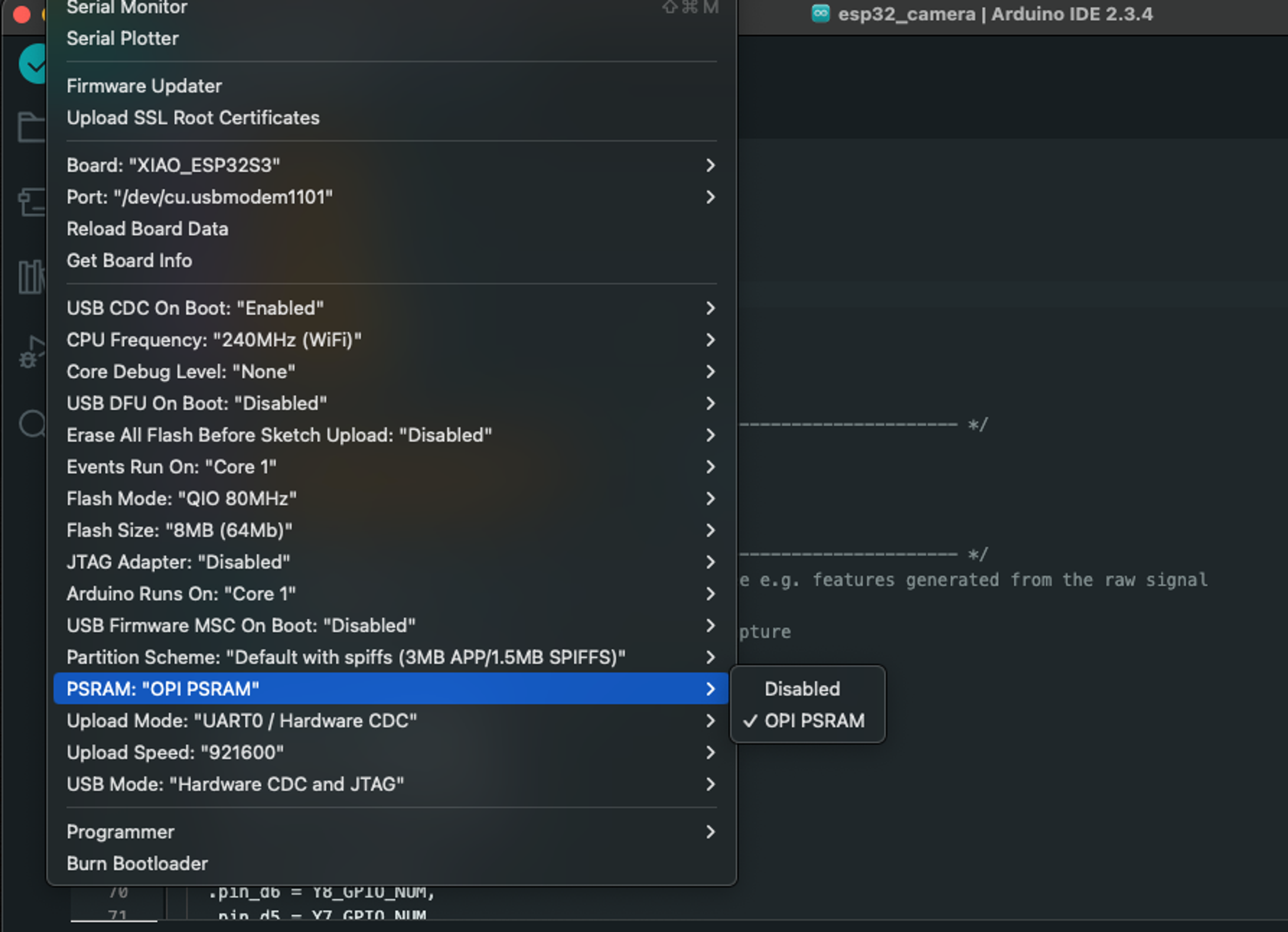
We also needed to enable PSRAM in the Arduino IDE so the device can efficiently process image data.
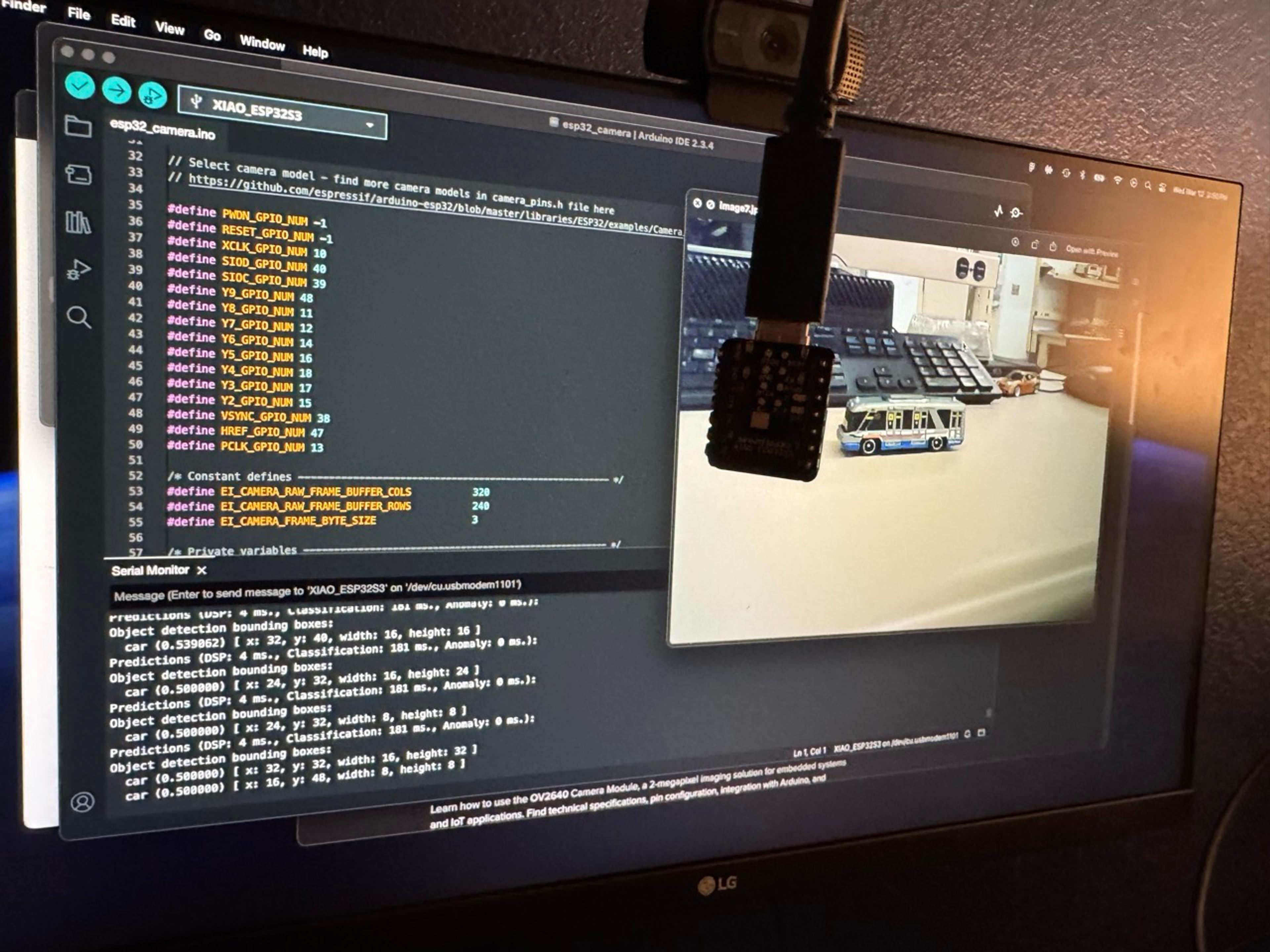
We then flashed the board and tested the model's predictive ability. Since I did not have any toy cars on hand at home, I tested the model by displaying images we used for model training, which showed that the model is able to identify toy cars.
Finite state machine
The final step of this project involved creating a finite state machine (FSM) that is represented as a traffic light. The FSM needed to handle four states: 1) car go, 2) car wait, 3) pedestrian go, and 4) pedestrian wait.
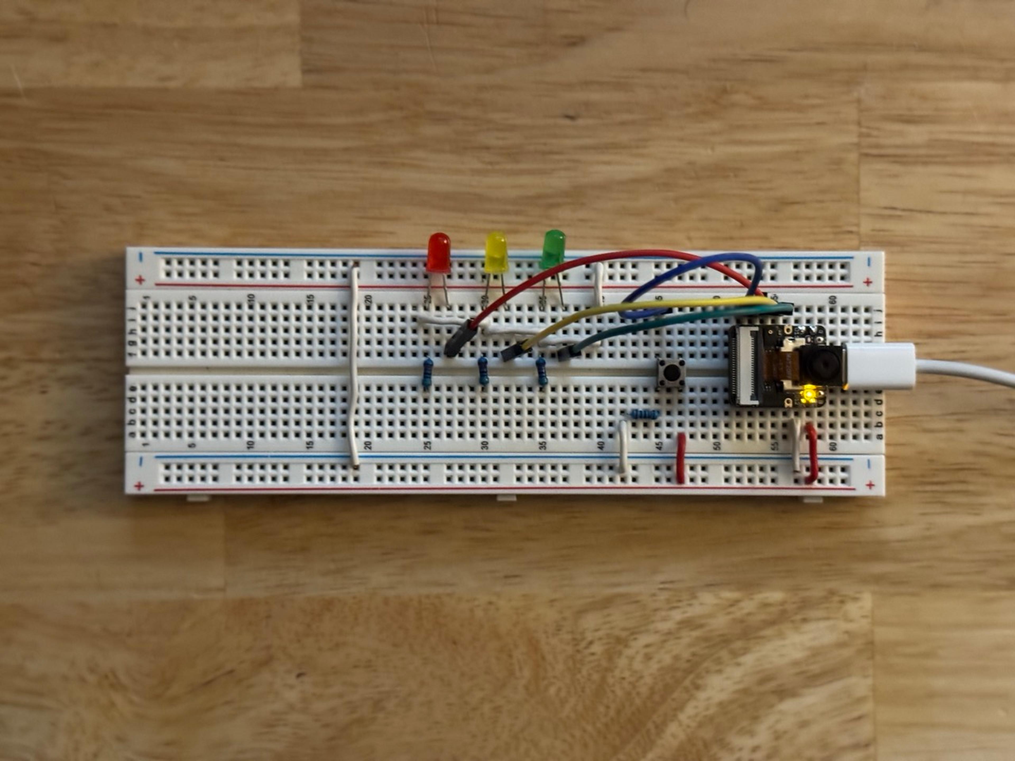
We replicated one of the example circuits featured on this webpage as a starting point for our project. This circuit is comprised of the XIAO ESP32S3 Sense, 3 LEDs (red, yellow, and green), four resistors (3x 470Ω and 1x 1kΩ), and a push button. We also used the builtin LED of the microcontroller to handle the pedestrian signal.
We tested the basic functionality of the FSM before hooking up our model. This allowed us to debug connection issues before introducing the additional complexity of our model code. The test program (available here) simply activates each LED relative to the number of button presses.
Once our circuit was wired correctly, we then modified the model code to include logic for activating LEDs based on the presence of cars and button presses.
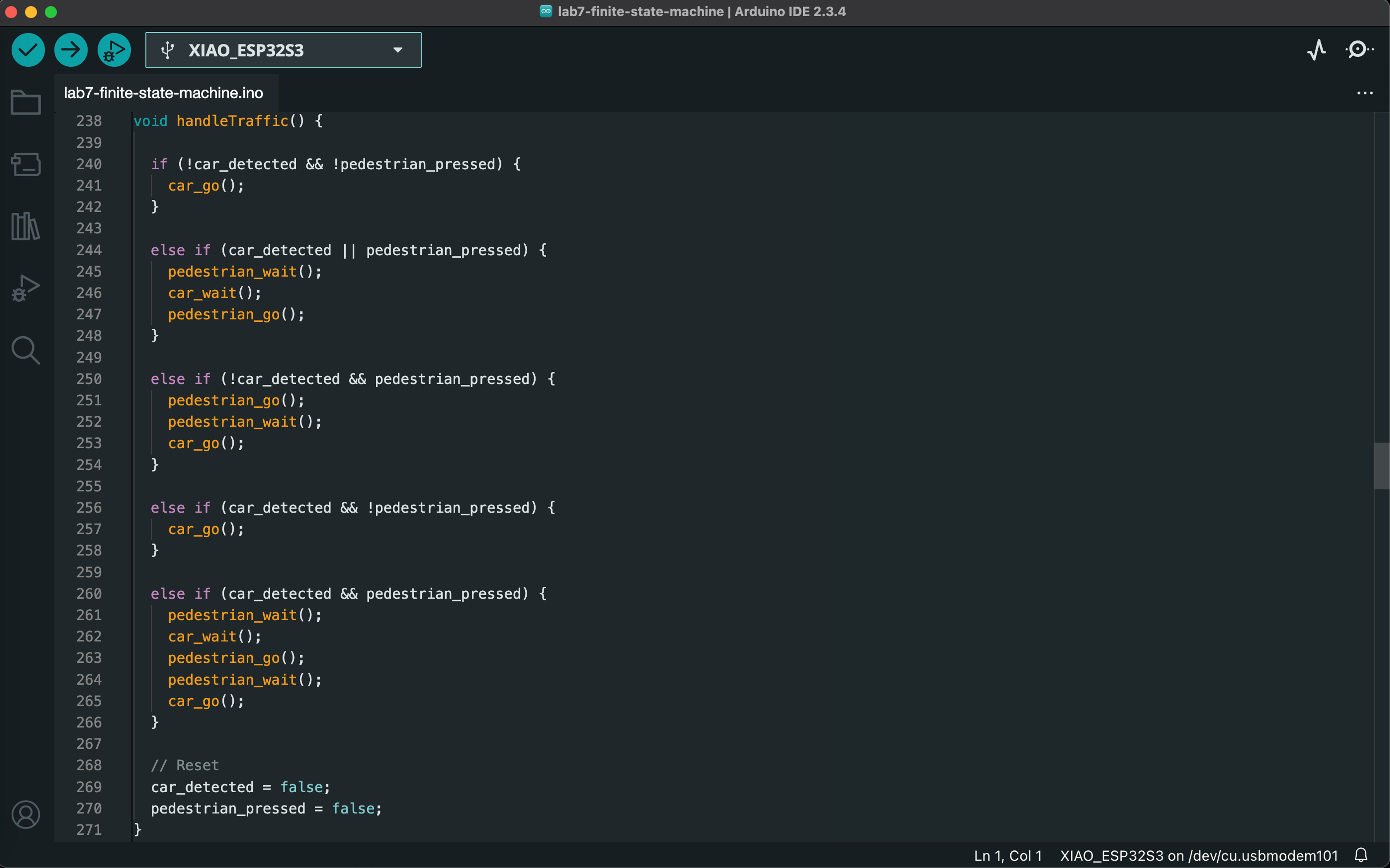
In general, button presses and each of the four states are managed in separate functions, and the logic for calling each function in appropriate sequences is handled within the handleTraffic() function.
The screenshots below shows how the core FSM logic calls relevant functions for each state. The final code for the FSM is available here.
Demo
Since I did not have any toy cars on hand, the demo video below shows how the model responds to a variety of static images on screen. A mixture of car images used for model training, non-car images (e.g., house), and car images not used for training are tested in the demo.
Note: the white balance fluctuates throughout the video, but you can still generally see what is displayed on the screen.
Downloads
All of the files used in our project are available here.

